Latest Event Updates
Porting MZR to android (NDK)

Recently I spent some time porting MZR to android and wanted to do a quick write up of some of the challenges I encountered. I’m no android expert so all of these were news to me.
A bit about the code.
First things first. MZR is written in C++ on a custom cross platform engine. The bulk of the code is written in C++ with a thin driver/glue layer per platform. My engine supports PC, iOS and now Android. It’s very easy to add new platforms. However, as many of you who’ve done this engine type of thing know, each platform comes with time consuming maintenance work afterwards.
Here’s a list of things that go in that platform-dependent layer:
- low level basics – core types, threading primitives
- low level IO support – file systems, input devices
- low lever render API – PC(DirectX), iOS (OpenGL ES)
- low level sound API – both PC and iOS use OpenAL
- networking – platform specific APIs for fetching data over http, socket based stuff, etc
- other non-essential stuff (from game point of view): social platforms, store and billing support, etc
Important to stress that the platform bits are contained to that layer. No game code references low level platform APIs. Everything is accessed through a platform-independent internal API that in turn talks to the platform specific code. On PC that is C++, on iOS it would Objective-C and on Android Java/JNI. This ensures that the game code works the same on all platforms and changes to platforms don’t trigger changes to game code.
Note: this may seem an unnecessary layer of abstraction but I do use certain techniques that allow me to bypass indirections and keep performance benefits without introducing dependencies to platform specific code [possibly warrants a post of its own].
Porting to Android
Ironically the most daunting part of the whole process of porting MZR to Android was the project setup. I knew I had to use Android NDK so I can make use of my C++ code base. However, how does a full project get set up with both Java and NDK, what are the right ways to set up both build environment and Eclipse… all down to reading a lot of tutorials, internet posts and trying things out.
My final setup ended up with:
- Eclipse project for the game. The Eclipse project only references the Java code, the C++ code is elsewhere.
- Android.mk make-file that references all the C++ sources compiling to a single .so library
All C++ debugging was done using custom tools and printf. In the end I couldn’t set up Eclipse to behave with my folder structure, building and debugging. Main problems here included the source generating a lot of errors by the automatic Eclipse compilation and then refusing to build the project. The Android.mk file had all necessary include paths and built correctly.
Once I had the environment set up, it was down to writing some code.
Core Basics & OS
Core basics were fairly easy to port. I use pthreads so nothing new there. Everything ported without issues.
However, I did get a nasty surprise in the atomic increment/decrement intrinsics encapsulation. On iOS the atomic inc/dec return the new value after the operation while the Android equivalents return the value before the operation. Something to watch out for if you ever do this kind of low level porting.
File systems. Here on iOS it was all down to getting the right file system “root” folder and then leave it to standard C libraries to do the job. On Android however there are two types of storage file systems in my engine – one to read assets from (AssetFIleSystem) and one to save data to (SaveFileSystem). Fortunately I already do this separation in my code when I read assets and save game data. That didn’t present a problem beyond the android implementation details.
The asset file system is built on top of AssetManager. I had to pass the AssetManager down to the JNI code from Java and then use it in the platform specific Android code of the engine. The save file system just has a path to the target folder and uses standard C libraries code.
JNI or how Java and native code talk to each other
If you write stuff with NDK, you will inevitably need to do some JNI. Theoretically you can write an android game entirely in native code. However, in practice every third party SDK for android comes as a java library, including the ones provided by Google.
Nothing to worry about there though. JNI is not hard and is well documented.
Here’s some gotchas that caught me out.
Native -> Java
On the Java side just write your classes as you normally would – all the work is then handled in the native part. I tend to use static methods mainly to keep things simple.
1. Cache your methods at load time. You need to execute some code to locate the Java class and method so later on when you want to invoke that method you can use these “handles” to do it. It’s a good practice to do this in your JNI_OnLoad function. The JNI_OnLoad function is called when your native (.so) library is loaded.
2. Make sure you are familiar with how the type names works so you can produce the correct signature for your methods. Otherwise you’ll struggle to find them even though the name is the same and the class is there. Also pay attention to the return type of the method because that mandates how you invoke that method.
For example, invoking a static method that has a void return type would be:
env->CallStaticVoidMethod(classMyClass, methodMyMethod);
While invoking a method that returns “float” would look like this:
float myVal = env->CallStaticFloatMethod(classMyClass, methodMyMethod);
3. When you locate your class and cache the handle, you need to get a global reference to it or it can get moved and then you are left holding onto a dangling pointer.
jclass classMyClass = env->;FindClass( "com/fc/mzr/MyClass");
if (classMyClass == NULL)
{
    FAIL("Can't find MyClass class.");
}

//get global reference to my class
classMyClass = (jclass)env->NewGlobalRef(classMyClass);
4. Make sure the JNI environment you use is attached to the thread you are calling java methods from. For example, in my code a run a number of threads, mostly for IO – file access, networking, etc but also for stuff like sound, music, etc. If you don’t do that you may get crashes that sometimes can be difficult to trace and seemingly inexplicable.
You can ensure the JNI environment is attached to the tread like this:
JNIEnv* JNI_GetThreadEnv()
{
   JNIEnv *env = NULL;
   bool isAttached = false;

   int status = g_JavaVM->GetEnv((void **) &env, JNI_VERSION_1_6);
   if(status == JNI_EDETACHED)
   {
       status = g_JavaVM->AttachCurrentThread(&env, NULL);
       DEBUG_LOG("GetEnv: attach status: %d", status);

       if(status != 0)
       {
    	   DEBUG_LOG("GetEnv: failed to attach current thread");
           return NULL;
       }

       if (status == JNI_EVERSION)
       {
    	   DEBUG_FAIL("GetEnv: version not supported");
       }

       isAttached = true;
   }
   else
   {
	 if (status == JNI_EVERSION)
	{
	   DEBUG_FAIL("GetEnv: version not supported");
	}
   }

   return env;
}
And then your calling code would look something like this:
JNIEnv* env = JNI_GetThreadEnv();
env->CallStaticVoidMethod(classMyClass, methodMyMethod);
5. Make sure you complete your Java execution quickly and return control back to JNI, especially if you have further code that uses that JNI environment in the same function – it won’t stay attached to that thread forever. I make it a practice to have blocking code in the Java part be executed in another task and then callback when long blocking operations are expected.
Java -> JNI
Calling native methods from Java is somewhat easier to set up. You need to declare methods as native in the Java class and then declare them in a very specific way in the native source.
1. Declare the methods in native code as C signature and with the correct name. Curiously the dots in the class path package name become underscores. The ‘extern “C”‘ part is really important, especially if you are using C++ – otherwise JNI won’t find your function.
extern "C"
{
	//mappted to class called MyClass in pacakge com.fc.mzr and the method is called myNativeMethod
	JNIEXPORT void JNICALL Java_com_fc_mzr_MyClass_myNativeMethod(JNIEnv *env, jobject obj, jstring myStringParam);
}
2. Don’t make assumptions on what thread you are once your JNI native methods are invoked. I spawn threads on the Java side to do async operations like Facebook requests, so the callbacks often come from another thread.
General JNI
Your native code is compiled to .so library that is then loaded by the Java code. You will have to put some code there to load your library. If you have multiple .so libraries that depend on each other then you need to load them in the correct order otherwise you may get a run-time linking error. This is not a 100% on all devices so take care because it may be that your device is working fine but others crash on start because of this.
And now some input multi-touch FUN!
Input was fairly straightforward. I handled the input in the Java part of the code and handed it over to the native part. I did have some problem with events being handled on a different thread to main loop. I ended up caching the events and picking them up once per game frame to ensure all events were handled consistently.
Beyond that there is a manifest setting to enable multi-touch support and the code for support multiple touches may need some care. It certainly took me some time to get it right but I attribute it to me being new to it rather than any gotchas. It all makes perfect sense now.
OpenGL ES is easy… oh wait… what was that bit about the context?
My OpenGL ES code that I use on iOS ported directly with minimal changes to Android. It just worked. There was little need to debug or fix things.
However, there’s a nasty surprise for Android developers with OpenGL ES. When an Android app is suspended (pressing the home button) it would lose the OpenGL context. That means that all resources referenced by the app are lost and the app needs to reallocate/reload all of that once the context is recreated.
MZR uses a lot of dynamic geometry and render-to-texture surfaces. Not only would I have to reload all static resources (like textures) but also recreate all resources that were dynamically generated such as old mazes, pre-rendered texture atlases, pre-rendered signs, etc.
In Android (I’m not sure which version this was introduced in) there is a method on the GLSurfaceView class called “setPreserveEGLContextOnPause”. That supposedly keeps the context so that it survives the app being suspended to the background although it doesn’t guarantee it will be back once the app is resumed. I used that – it works. For the most part the context is there – however I have gotten reports that on some devices it isn’t.
I also made sweeping changes to MZR to make it reconstruct all resources so that it can survive a “lost” context. I did hit some problems with that. I’m assuming this is completely my own fault but I was unable to completely trace the issue on Android. On both PC and iOS I was able to nuke all resources and restore them again but the android version just wouldn’t work. I had limited time to invest in this issue so I left it at that. If there is a need to fix that entirely I’ll look into it again.
OpenAL works a treat but there is a… lag!
I use OpenAL on iOS and PC. The code is the same. I have a high-level audio engine (that uses XACT as authoring tool) that’s built on top of that.
My first reaction was to use one of the Android sound APIs but it looked like a lot of work compared to a tested OpenAL implementation. I found a library called openal-soft that has an Android port. Dropped that in (skipping all the build/setup details) and it worked perfectly…. apart from the half a second delay between triggering a sound and the sound actually being audible. The delay would vary with different devices.
At some point I was going to ship with that lag in but in end thought I’d try the native android audio library – OpenSL.
OpenSL ES is very different from OpenAL. It has a COM like interface and it required some getting used to. This tutorial proved very useful.
I had to make a fresh implementation of my low-level sound system interface using OpenSL.
To play compressed music I used the MediaPlayer in the Java part of the code. I had a policy to cache these players on iOS so that I can have a zero-seconds start of the music playback. On android however there is (can be) a limit of available players at any given moment so you could end up with the player failing to play your music track. I was hitting this problem at some point.
Android devices come in all forms and shapes
MZR is a portrait game. I could limit the orientation to “portrait” in the android manifest. However, that doesn’t guarantee the resolution or the aspect ratio of the main display buffer.
This means that MZR suddenly needed to support all sorts of resolutions, not just the standard iPhone and iPad ones. MZR is mainly a 3D game so that wasn’t a big problem for the game content.
Front end 2D interface however is another matter. I have a 2D layout tool where I can layout each of my 2D interface pages that I then load and display in-game. To support an unexpected resolution the tool supports anchoring. Anchoring is used in many windowing systems to control the behaviour of UI elements when window panels change size. For example if a button is anchored to the left of the parent panel, it will stay relative to the left edge of that panel. In my tool I can anchor elements both horizontally and vertically. Respectively they can be anchored left, centre or right and top, centre and bottom. That solves most problems with small variations of the resolution and aspect ratios.
One final glitch is font rendering. In my engine fonts try to stay pixel perfect in 2D unless explicitly overridden by the game code. Fonts would look really small on screen for higher resolutions. I had to introduce multiple font sizes and switch at certain resolution thresholds to keep the fonts crisp and relatively well sized.
Android devices come in all muscle shapes and sizes
MZR is a fairly demanding game. Despite its simplicity it renders quite a bit of geometry and overdraws the screen with transparent effects. This could prove particularly troublesome especially if the hardware is slightly out of date or/and resolution is really high.
To address this on iOS I had a predefined list for each version of iOS device with graphics quality settings. Some features would be enabled on some and disabled on other devices. For example iPhone4 has hardly any graphics features enabled and iPhone5 has all the bells-and-whistles… with original iPad Mini being somewhere in between.
For android this was not a practical approach. With potentially thousands of devices I wouldn’t be able to create such a list. To solve this I introduced a number of features:
- a graphics settings page in the options menu – the user can go and switch graphics options on/off to tweak their performance
- an automatic measurement of average and lowest FPS (frames-per-second) and switching graphics options off if that FPS measurement drops under certain limit; that way the app always starts with maximum settings and after a couple of runs (if FPS was not satisfactory) dropped the settings to recover some FPS
- server solution – after every run the game would upload average FPS info to the server anonymously for that device (and settings); the server can then aggregate the data and find an optimal preset of settings for that device type;
- server presets – every time the game boots it contacts the server and asks for graphics settings presets – if presets exist for that device then they are downloaded and set as default – turning this process into self-accumulating list for thousands of devices
Immersive mode & full screen
When running a fullscreen game on android you will want to hide the status bar. Also some android devices have their home and back buttons at the bottom of the screen – (action bar)?
There are a few examples on the internet how to handle this but what I’d missed out is that I have to set up an OnSystemUiVisibilityChangeListener which is a handler that gets called when there are changes to the visibility settings of the app. In that handler I’d have to set the appropriate flags to make the app full screen.
You can read more about Immersive mode here: https://developer.android.com/training/system-ui/immersive.html
Check it out!
The game is now available on the Google play store. Be sure to check it out:
https://play.google.com/store/apps/details?id=com.funkycircuit.mzr
That’s it for now.
Thanks for reading!
MZR Update 1.1 Released

MZR Update 1.1.0 was just released on the AppStore.
So what’s new in this update:
Super Power-Ups
There is a new “super power-up” mode in the bonus stage allowing the player to get a higher highscore. That mode was in development before main game release but got put on hold so that I can get the game out on time. It introduces another type of maze solving – a classic iteration on the multiple overlapping mazes where you need to choose one entrance that would lead you to to the destination you desire. As with the bonus stage there is no failure here – the player can only gain. They have to quickly asses what powerups are on offer and choose the right entrance.
Retina Graphics
This is a result of some of the work related to the Android version of the game. MZR now supports retina resolutions giving the game a nice crisp look if the device can handle it.
Country Scores
The main screen/leadergrid gets a facelift. Countries now have full names (as opposed to alpha-2 country code) and are better spaced on the field. As a result not-all countries are visualised but it looks a lot more presentable.
Finally, congrats to Australia. At the time of release of the update Australia was in the lead with the score of 812 – amazing achievement.
Other Fixes
There have been many fixes and improvements in this update such as: tilt control centring, graphics options, spelling mistake fixes and many more.
What’s next?
There’s an Android version of the game which is very close to release. So watch that space.
That’s it for now,
See you later!
MZR: Music synchronisation with a band-pass filter
This is how this game MZR happened to be. I always wanted to have visuals synched with music. That was integral part of the game idea so much that after some initial failures to get that going I gave up on the whole game for about couple of months.

Part of my inspiration came from early encounter in the XNA scene with ColdBeamGames’ game Beat Hazard. (http://www.coldbeamgames.com/). An excellent example of how music synchronisation of visuals and game play can work really well. Definitely a direction I wanted to go towards although ColdBeamGames’ stuff in that area is just on another level.
Again this is a vaguely technical post. It’s going to be fairly simple stuff thought.
In order to synchronise visuals with music you want to be able to turn a waveform signal (audio signal) into a signal that drives your graphics. This can be done in couple of ways (that I know of):
- processing the raw audio input and extracting the amplitude of different frequencies (drums would be a fairly low frequency – for example 100Hz, voice is in the middle ones, etc). Then using that result signal to drive graphics.
- tagging – visualising the wave form and using a tool to place various events on the track, matching the beats and various other music facets. During game you can then synchronise the tag stream with the music stream and have the tags drive the visuals or game. I imagine that’s how most “guitar hero” games are done.
Both approaches have advantages and disadvantages. Automatic processing can handle all sorts of music and produce fidelity you can’t ever achieve with tagging. On other hand Automatic processing detects frequencies – it’s simple as that. If you want anything more complex that is matched by something like a song chorus or a specific music phrase – you want tagging. Also nothing stops you form using both approaches together.
In MZR I use automatic processing. In this post I’ll describe how got there.
I tried FFT first
Fast Fourier Transform is (better explanation from Wikipedia) an algorithm that can compute the discrete Fourier transform. A Fourier transform is one that can take a signal from time domain (amplitude over time waveform) to frequency domain (amplitude of frequencies). In essence you provide an array of values which is the sound (at 44KHz you get 44000 values per second) and you get an array of frequencies. In the frequencies array each item is the amplitude of that frequency.
You can find FFT implementations on the internet – there are ones in almost every programming language I can imagine. It’s a known numerical recipe [points for those who got this pun ;)].
So, what do you do with this array of frequencies?
- find the dominant frequency – this is as simple as finding the array item with the largest value
- lookup a frequency range that you are interested in
- visualise it – in a traditional graphic equaliser the array items would each be a bar and the item values would be how high those bars are lit up
So why didn’t I use this? Where’s the gotcha with using FFT?
FFT is successfully used for this exact purpose. However I had couple of issues with this, some of them unrelated to the algorithm.
First and foremost I had made a mistake with my wave forms array calculations. Due to that I was feeding corrupt data into the FFT and was getting results that were really wrong. As there are complex numbers involved and I don’t fully understand it I assumed I had implemented it wrongly or was using it incorrectly. The result after hours of experiments and visualisation was to abandon this solution and look for another one.
Another, not so valid reason is that FFT can be costly to calculate. I grew up in the ’90 when we were counting every unorthodox operation and if simpler solution was available that could do the job that was the preferred solution. Today’s computers even on mobile devices are pretty powerful and wouldn’t bat a eyelid at this algorithm.
Not long after I had a chat and sought advice from a friend of mine – Neil Baldwin. He is far better informed in all matters audio, audio programming, audio electronics, music, etc… besides being an all round fantastic fellow. Checkout his site, especially if you like chiptunes and NES stuff – you wont be disappointed.
Anyway, that’s when I learned about band pass filters.
Band-pass filter
You have probably heard of low-pass and high-pass filters, right? If not, a low-pass filter is one that once applied leaves only the low-frequencies in the signal. I’ll leave you guessing what frequencies a “high-pass” filter leaves.
A band-pass filter is similar to the low and high pass ones but can be applied for an arbitrary frequency band. So you can say stuff like apply band-pass for a band that is centred at 440Hz and covered 200Hz each side. See the graph image at the top of the article and the link under it – that has a good and more in-depth explanation of what a band-pass filter is.
I believe my implementation was based on this internet post and code sample on the topic.
I thought the band-pass filter was a lot simpler to implement than a FFT and a lot easier to understand. I used it instead of my FFT implementation. No joy! That’s when I left this venture and took a break.
Couple of months later…
… I suddenly realised that the problem wasn’t with the FFT or the band-pass implementation. I had made a mistake of how I calculated the wave data size and converted the stereo channels into a mono stream to process. Once that was fixed, everything fell into place.
It’s good to mention couple of things about debugging this stuff, even though I may not be the best person to advise on that given the above story. At least I knew I was doing it wrong and it was because I did this:
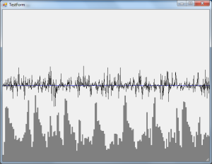
- visualise your input stream and output stream – I wrote a quick app in c# that drew the wave data and then overlay the processed on top – see if they matched. That’s how you know the algorithm is working.
- play the music on top visualising the playback time to see if the processed data matches the music playback in any usable form. That’s how you know you can use the output you are getting.
How did I end-up not spotting the problem then if I had such visualisation. My mistake was such that the calculated input signal data didn’t match the length of the music. I was visualising only the start of the music track (a few seconds) and things looked ok-ish… however once used in game things quickly went wrong and I couldn’t figure out why. Once I visualised the whole music track I could clearly see how the stream was ending well before the end of the music track. I guess the moral of the story is – if I have debugging tools I should use them in every possible way, not just in the one narrow minded approach I started with.
Actual game data
Once I got this working, I could see two ways to use these filters:
- pre-process the data offline and bake it into a file, then load in a game and use it synchronised
- use the live audio stream as sent to the audio output of the device and process that
I chose the first method. My decision was mainly driven by having to implement the audio output capture on multiple platforms. The iOS capture looked complicated enough. Plus, I wasn’t planning on changing music tracks or using the user’s music library (like Beat Hazard mentioned above).
I run 4 bands band-pass filters offline on all music tracks found in the game. I store the result at 60fps – my target frame rate. Each item is a vector4 with x,y,z and w being the output for each band – so I got 60 vector4 per second of music.
At game run-time I load the pre-processed data and track where the music playback has reached to – then I sample the vector4 value and attenuate it gradually in game.
That way in-game I always have a vector4 value representing 4 frequency bands that I can synchronise my visuals with.
Finally
Most of the time you don’t have to deal with this. I mean signal processing is fascinating but it’s hard to get right. Most game engines these days would have built-in functionality to give the FFT of an audio stream. That’s right. For example Unity provides something called AudioSource.GetSpectrumData. Check it out.
That’s it!
See you next time.
MZR leadergrid programming tricks

In MZR (now on App Store: http://bit.ly/MZR_Game) there is an alternative approach to the concept of leaderboards. As the height of the player’s tower is the score we decided that it might be a good idea to have everyone else’s tower around. See your friends and their scores at a glance. As they are all represented as square columns on a grid I call this the MZR leadergrid.
User can browse around, zoom in or out and see the global picture – scores aggregated by country as well as their friends.
In this post I’ll talk about the leaderbaord implementation. In general it’s a collection of programming tricks and shortcuts and I wanted to describe some of those.
Most of the techniques are aimed at providing visual complexity while reducing the number of draw calls. High number of draw calls is possibly the main thing that would hurt your performance – any opportunity to reduce that number without impact on quality should be considered.
The implementation of the MZR leadergrid score representation is split in two parts.
- The local grid where every tower is an accurate representation of a real active player.
- The global grid where a representation of the global leadergrid is rendered based on aggregated data from our servers.
Local grid
Local in this case refers to the locality of the other users’ towers to the centre player tower. There is a grid of 9×9 towers around the main one.
This local grid, contains a few types of entries:
- friend entries – these are the towers of friends logged in Game Center or Facebook. Every friend gets their avatar picture on top of their tower, as well as their score
- active player entries – there are towers of players who have played the game recently. The idea is to get a selection players who are currently playing the game.
- global grid entries – these are entries that could not be filled by friends or active players and are sampled in a similar way as the global grid one (described below)

In a way this local bit is the “friends” section of a normal leaderboard but extended so it can always fill 9×9 matrix.
This local grid is the immediate vicinity of the player playing field and as such visible during gameplay. I also wanted to indicate on the nearby columns (towers) how the current player score compares to them.
The local grid is accurate. Every column (friends and active players) is an actual player with their score as reported by our servers. Every time a player submits a high-score to the servers, it is stored in our database and then reported to the player’s friends when they play.
Rendering of the local grid
All of the columns in the local grid are a single rendering mesh. That allows efficient draw call submission – 1 call is better than 9×9 calls. The writing and avatars on top are additional draw calls as they are translucently blended on top. That also allows me to dynamically alter/grow columns as players upload higher scores. Each column is always in the same place in the vertex array so I can calculate what part of the vertex array I’m changing when the column grows.
A similar approach is taken with player scores. A single draw call renders all players score. They use the same font and can change dynamically. That’s possible because I always leave space in the vertex array for 4 digits. By using degenerate (zero area) triangles I can display scores that with less than 4 digits while maintaining vertex count for the full 4 digits.
Finally the avatars. The avatars can change at any time as player logs in to Game Center or Facebook and gets lists of friends… and their avatar pictures are downloaded from the respective network. Furthermore, to optimise the draw call for those avatar images they need to be in the same texture – not separate textures. Again a single draw call is a lot better than 81 (9×9) ones.
To achieve that I pack all images into a dynamic texture atlas. I use a render-to-texture technique to pack each avatar picture into a separate place on the same texture. Then I just need to update the display avatar mesh with the right texture coordinates of where that avatar image finds itself in the final atlas texture. A bonus of this atlas rendering is that I can apply a custom shader effect to the avatar images achieving the specific MZR look they have.
Finally I have the hight indicators rendered on the closest friend columns indicating how high the current player run has reached. At the same time if a local grid column is overtaken, it would flash briefly by changing the colours of the appropriate vertices in the grid vertex array.
Global grid
The global grid is everything outside the 9×9 local grid. It repeats infinitely the space so the user can scroll around in any direction when they browse. By repeats infinitely, I mean that the camera is telported back once it reaches certain limit – wrapping back to the opposite side of the area – that gives impression of endless scrolling.
The global grid is not a 1-to-1 representation of all the players in the world. It is a statistical representation. This is done for couple of reasons:
- to reduce the data transfer between the app and our servers
- to show the player a bigger picture about the scores of the world.
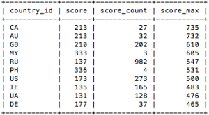
Scores are aggregated by country on the server. This table shows the top 10 countries (by max score) at the time of writing of this article. (score = average score, score_count = number of players submitted score form that country, score_max = the top score form that country)
To achieve that I do a certain aggregation on the server with respect to players scores. At regular intervals a routine runs that calculates stats for every country in the world. The stats calculated are number of players from that country, the average score for that country and the maximum score.
The game client downloads the country score stats from the server. The global leadergrid is then rendered using that information. You can look at this from a data compression point of view: it’s a loss compression method where the data aggregation is the compression and the visualisation is the decompression part.
In terms of visualisation each country looks like a small mountain of columns. The more people play in that country the larger space it occupies. The top score for that country is the highest point of the mountain. The average score of the country dictates how “sharp” the mountain is. If the average score is low (a lot lower than the max one) then we get a mountain that’s fairly pointy – naturally the people with high scores are not many. If the average score is high, then we get a meatier mountain as there are more people with relatively high scores.

I achieve that by using a power function to approximate the curve slope. I take the average score (av) and the max score (max) for a given country and calculate the ratio as av/(max*0.5). That way score average that is half the max score for that country would mean a power of 1. Say we have average score of 50 and max score of 100 – give the formula we get 50/(100*0.5)=1. We then use the function f(x) = 1-pow(x, av/(max*0.5)) to get the height at various point of x where x is the distance of the sample point form the centre of the country region.
Note: the mathematical ground behind this was if we imagine these mountains as cones (or a swept/revolved curve that makes a kind of a strange cone) then the volume of that cone would be the total added scores of all players playing. That can be found by calculating player scores x average score. We know the height of the cone (max score) and the radius of the cone (number of player playing). Having the radius and the height of the cone the unknown would be the curve which swept would dictate the volume of the “cone”. The connection between the curve and the cone volume would be an integral of that curve over a circle.
Solving this however goes beyond my mathematical skills and seemed extremely OTT when I had a sensible approximation already.
Global grid country field

Once the country scores have been downloaded from the server. They are inserted into a CountryField object that places them on a plane and uses a relaxation algorithm to make sure they are spaced evenly according to their respective radius. After that I can query the CountryField at any point in the world and it will return a height for that point based on what countries overlap and influence that point. The relaxation is seeded randomly so that every time a user gets the countries from the servers the global grid looks different.
When sampling at a certain point I consider all countries that the sampling point overlaps with. Then I apply a calculation described above and take the highest sample position. Layered on that is a deterministic noise function so that the score mountains don’t look uniform.
The rendering routine then uses this CountryField object to sample the heights for each of the global grid columns.
Adaptive subdivision
Rendering all global grid towers in one go proved slow – too much geometry to update at the same time. I opted out for an adaptive subdivision technique where if columns are close to the camera then they are rendered if they are further away they get converted into a bigger column that’s the average of their height (it’s actually biased above the average as that proved better looking). This is done on 3×3 columns basis. As camera moves around some of these combined columns split up dynamically and other coalesce. This combined with some non-linear interpolation gives the unique MZR look when user is browsing around.
This adaptive technique also means that geometry rendered is kept under control.It also allows the adaptive algorithm to work on only fraction of the geometry to interpolate and update the vertex array. The entire global grid is a single mesh and there for a single draw call.
Country names
On top, like clouds, are rendered the country initials (alpha-2 country code) and the country top score. This is again a single mesh so I can render that in a single draw call.
Learnings
MZR has unique look when it comes to leaderboards. In some ways however it is a bit “style before function”. That’s ok. MZR has always been about trying something new, be willing to go where traditionally games have done stuff another way.
With that in mind here’s what I think could be better:
- No easy way to compare. In a traditional leaderboard user gets a list of entries with them inserted in the middle. They immediately know who is ahead of them and behind them. This information is more difficult to read in MZR. User gets a bigger picture view but details remain a bit hazy – the details are still there but not so easy to compare.
- No easy way to compare country scores. User has to browse around Its’ been fun to watch different countries take the lead (as of writing of this post Canada has the lead) but it would have been better to have a clear indication of who is in front.
- In retrospect just using alpha-2 country codes make for a more alienating experience. Using something like full names or flags would have work better.
That’s it. If you are interested in reading more about any of the areas I describe, do let me know and I can write that up in more detail in a separate post.
See you next time.
MZR is on the App Store!

Well, I woke up yesterday to a surprise. MZR had been in review for the last six days and got approved by Apple yesterday morning.
As I hadn’t put a release date, it automatically got released on the App Store.
You can find it here: MZR on the App Store
You can download it and play it for FREE! Seriously, do it now.
If you are a journalist and want to talk to us about it. Checkout out the MZR press-kit
Why free?
Before today Funky Circuit had four games on the App Store, some of them (the ones I didn’t design) are really damn good games. They are games that matter. Games that teach something, games that have something to give to the world.
Those games before MZR were also games that tried to make money in some way. It’s only fair. We [the Funky Circuit people] put our work and resources into it and we wanted to get something back. Each game followed a different business model – one would be free with content in-app-purchases, another one would be paid, another free-with-ads, etc. We wanted to try things.
As some of you know, MZR was a solo project. I wanted to make something that’s completely me. Something simple, cool, fun. In many ways MZR is a lot more pure time-waster-entertainment than any of the other Funky Circuit games. It’s just cool, nothing else. I could argue that it teaches you how to find the shortest route in a maze but that’s just an afterthought.
Finally, getting downloads on the App Store is really difficult. Especially without a dedicated marketing effort or the indie equivalent of extreme networking at events and social media.
So, having that in mind I wanted to make it really simple to download and play this game. I want as many players to try it. No barriers to entry, no payment, nothing. At this point people playing MZR is more important than MZR making me any money whatsoever. If numbers grow big that may change – there are server costs involved. But for now it’s all free.
What happens to this blog now?
I will continue posting here. Technical stuff and occasional design post. I have several posts half written, but it is very difficult to both develop a game and write a blog in the same spare time… maybe now I’ll have more time.
I see this as the MZR supplement that is contributing something to the world, other than just being cool 🙂
So watch this space.
And download MZR at: http://bit.ly/MZR_Game
See you next time.
Blending and Transitioning Camera Behaviours

This time I’m going to talk about an approach I’ve used successfully on multiple occasions in several companies and home projects. I use it to manage multiple behaviours, blend and transition between them.
I’ve used this system for animation blending and camera control in the past. However, if I can represent something as a state structure and want to blend/transition between different behaviours that operate on that state then this is my “go to” solution.
In MZR I use this approach for my camera system as well as a system that adds additional camera effects – shakes, wobbles, etc. They are both independent: the camera may have a “focus on point of interest” behaviour to control it while the effects can change independently of that giving me a wider variety of visual experience.
The main motivation behind a system like that is that we want to be mostly concerned with directing the system behaviour rather than be busy with the small detail of how that happens every time. I’m interested in when the camera transition happens, how long it lasts, what the new camera frame is, etc. I’m less concerned with what happens with the old camera setup and I’m definitely not keen on doing the same work every time a camera transition needs to happen, in terms of maintaining entities and writing code to manage their life time.
Ideally we want to write only the code that introduces changes in the system and have the system sort itself out afterwards.
First things first.
Couple of words about some code choices.
In order to get automation of allocation and deallocation of objects I make use of a smart pointer system. If you are working in a managed language environment (like C# for example) you don’t have to worry about that. However, for the purpose of this article if you see an object that is derived from BaseObject then it supports intrusive reference counting. And if you see SmartPtr<MyClass> then that adds value semantics to the pointer – incrementing, decrementing the ref count of the object to manage its life time.
In short it’s an automatic lifetime management system. If noone is pointing to an object it will get deleted.
The State
I use a POD type of structure to represent the state of an item in the system. In this example the we are doing a camera system so let’s represent the state as two points: camera position and camera target. You can use a position and orientation or any other combination of properties.
The state is important because this is the result of our system. It is also the data that we would blend. Any behaviours we have will aim to produce one of these states as result of their execution.
struct CameraState
{
     Vector3 position;
     Vector3 target;
};

CameraState BlendCameraState(const CameraState& lhs, const CameraState& rhs, float fraction)
{
    CameraState result;
    result.position = lhs.positions*(1.0f - fraction) + rhs.position*fraction;
    result.target = lhs.target*(1.0f - fraction) + rhs.target*fraction;

    return result;
}
The state can be anything. In case of an animation system the state can be an array of skeletal bone transforms, movement vector extracted from the animation and so on.
The Base Controller
Next, the basic building block of my system – the CameraControllerBase. It contains a state that we can get access to in order to find out the current state of the system.
class CameraControllerBase: public BaseObject
{
public:
    virtual SmartPtr<CameraControllerBase> Update(float fDeltaTime)
    {
         return this;
    }

    const CameraState& GetState() const { return m_state; }

protected:
    CameraState m_state;
};
The most important part of this class is the Update method. The update is where a derived behaviour would do the work by overriding that method.
The Update returns the current controller the parent entity would have after this update step. At the top level, let’s say the entity that owns the system, we have a pointer to the current “top” controller.
SmartPtr<CameraControllerBase> m_topController;
In the update part of this top level entity we want to update the current current top controller and assign to it whatever it returns.
void Game::Update(float fDeltaTime)
{
    ...
    m_topController = m_topController->Update(fDeltaTime);
    ...
}
By doing this we make sure that whatever behaviour is currently at the top controller will be updated and can delegate it’s position of “top controller” to one of it’s child behaviours it aggregates.
This is the driving idea behind this approach. Controllers can “suicide” themselves and pass the responsibility of top controller to another controller they hold a pointer to.
In this article I use the terms controller and behaviour interchangeably. My base building block is the controller – but some controllers have more complex functionality that is beyond the simple control/blend functionality of the system. In other words they have some game or domain specific function that is used to generate or process a state. I call such controllers “behaviours” to indicate their higher function.
The Blend Controller
The blend controller is a class that takes two other controllers (of unknown type but derived from the base one) and blends between them over time. Then it replaces itself with the second controller – the one it interpolates to. As it replaces itself with the “to” controller the “from” and the “blend” controllers are automatically disposed of.
It’s a transition.
class CameraControllerBlend: public CameraControllerBase
{
public:
    CameraControllerBlend(SmartPtr<CameraControllerBase> From, SmartPtr<CameraControllerBase> To, float BlendTime)
    {
         m_blendTimeMax = BlendTime;
         m_blendTime = 0

         m_controllerFrom = From;
         m_controllerTo = To;
    }

    SmartPtr<CameraControllerBase> Update(float fDeltaTime)
    {
         // accumulate the time
         m_blendTime += fDeltaTime;

         //update the two controllers; assign the result of the update them so the take over logic works
         m_from = m_from->Update(fDeltaTime);
         m_fo = m_to->Update(fDeltaTime);

         if (m_blendTime < m_blendTimeMax)
         {
              float fraction = m_blendTime/m_blendTimeMax;

              //use fraction to blend between the states of m_From and m_To
              //store the resulting blended state in m_state of base class
              m_state = BlendCameraState(m_from->GetState(), m_to->GetState(), fraction);

              // return this one as the current top controller
              return this;
         }
         else
         {
              //the blending has finished - return the m_To controller as one that will take over
              return m_to;
         }
    }

private:
    float m_blendTime;
    float m_blendTimeMax;

    SmartPtr<CameraControllerBase> m_from;
    SmartPtr<CameraControllerBase> m_to;
};
To trigger this transition we we have to replace the top controller with a newly created blend one that blends between the old top controller and a new behaviour.
void Game::BlendToController(SmartPtr<CameraControllerBase> ToController, float BlendTime)</pre>
{
      m_topController = new CameraControllerBlend(m_topController, ToController, BlendTime);
}
Easy. With just one line we can introduce new controller/behaviour in the system and have it blend in gracefully and clean up after itself.

A really nice property of this system is that if blend transitions come in close succession (before the previous blend has finished) everything works exactly as expected. By doing that we are essentially growing the three of objects with every branch being a blend controller pointing to either other blend controllers or behaviour. In the end once all blend times have expired we will be left once again with one top controller.
Sometimes we want to blend to a behaviour, stay at that behaviour for a while and then return to the previous one. I call that an “attack-sustain-release” blend controller. The controller blends to the “to” behaviour, stays there for “sustain” time and in the end returning the “from” controller and disposing of the “to” one.
Here’s how this “attack-sustain-release” (ASR) controller Update function might look.
SmartPtr<CameraControllerBase> CameraControllerBlendASR::Update(float fDeltaTime)
{
    // accumulate the time
    m_blendTime += fDeltaTime;

    //update the two controllers; assign the result of the update them so the take over logic works
    m_from = m_from->Update(fDeltaTime);
    m_to = m_to->Update(fDeltaTime);

    if (m_blendTime < (m_attackTime + m_sustainTime + m_releaseTime)
    {
         //calculate fraction as function of current BlendTime, attack, sustain and release times
         //fraction will stay in the range [0:1]
         float fraction = CalcAttackSustainReleaseFrac(m_blendTime, m_attackTime, m_sustainTime, m_releaseTime);

         //use fraction to blend between the states of m_From and m_To
         //store the resulting blended state in m_state of base class
         m_state = BlendCameraState(m_from->GetState(), m_to->GetState(), fraction);

         // return this one as the current top controller
         return this;
    }
    else
    {
         //the blending has finished - return the m_From controller as one that will take over
         return m_from;
    }
}
The fraction function returns a value between 0 and 1 depending which phase of the controller we are in. During “sustain” fraction will always be 1 for example.
Behaviour Controllers
We had a look at the blend controllers but what about the actual behaviours in the system? Well, that’s down to the specific system. That’s why our Update function is virtual, so that any derived classes can calculate the state in many ways not imagined by us at the point of writing the system.
For a camera system here are some that I’ve used in the past (Note: names are something I’ve just come up with):
- CameraControllerSnapshot – take a snapshot of a current CameraState and keep it still – in many ways that’s the CameraControllerBase with ability to expose the m_state for writing.
- CameraControllerFixedPointLookAtPlayer – one that keeps the camera in the same position but makes it look at the player and track them
- CameraControllerFixedDirectionLookAtPlayer – camera looks at the player from certain directions and moves position to maintain that direction as that player moves. Often such camera would be constrained by a box or geometry.
- CameraControllerRailsLookAtPlayer – this is sort of cinematic camera 3rd person action games would employ. It would constrain it’s position to a pre-defined spline (on-rails) and follow the player.
- CameraControllerRailsFixedLookedAtPlayer – this is a variant of the on-rails camera where there are two splines. One that defines the camera position and another one that defines the camera look-at point. This is used so that at any point the artist (camera man) knows what will be in the frame. We would then take the player position, find the closest point on the target spline and calculate the position spline accordingly.
I’m sure you can come up with a lot more camera behaviours. This is just a taste. As long as your Update function uses some logic to fill the m_state CameraState you will have a working system.
Non-transition blending
Not all blends are transitional. They don’t have to be timed and always expire.
We could have a behaviour that has two child behaviours – very much like our blend controller. However instead of time controlling our fraction we can control it from another parameter in code or data setup. That way we can dynamically control the degree in which each of the child behaviours contribute to the final state.
You can take this notion a step further and introduce several child behaviours that are all associated with a value on a line – for example one sits at 0, one at 0.5 and finally one at 1.0. Then the blend behaviour would be given a parameter “depth” and it would evaluate which child behaviours contribute to the final output. This I’ve heard that called a “depth blend”.
There could be other blend examples where the parameters are not linear. Any parameter set can be used as long they can be evaluated to result into a weight for their corresponding child behaviour contribution.
I’ve mostly used these in animation blending. For example, the depth blend could be used in character animation where we want to blend between two animation loops: running and walking. Based on the desired speed of the character we can derive a parameter that is the fraction between walking and running speed and pass it in as depth blend factor. The result would be an animation that is half walk and half run driven by the parameter we just passed in.
Another animation example would be the multi-parameter blend. Let’s say we have several animations of a character that is pointing [a weapon?] at different directions. Each of these animations is associated with it’s corresponding aim direction. Given a desired aim direction the system evaluates a function that results in an array of weights – one for every animation. Using those weights we can then calculate a weighted blend of those animations to got to a state where we have a character pointing at the direction we need.
Note: there is a lot more going on in character animation systems and I’m simplifying here to illustrate this method. A good animation system would need to compensate for different character speeds, foot planting, make additional corrections using IK solutions and so on.
In practice…
… I have a generic template implementation that I specialise every time I have to write one of these systems. The blend controllers are the same. The state, the state interpolation function and the behaviours are what differs between systems.
Sometimes you will need different interpolation methods than just a linear in transitions. You can add that to the blend controller and control it with a parameter.
Depending on the game that you are making you may even want to make the blending controllers be more context aware. Maybe you want your camera to always track the player no-mater-what. Maybe sometimes blending between two perfectly good behaviours you end up with a frame or two when the camera isn’t looking at the player. To fix that you could make a “clever” blend controller that blends between two controllers but keeps the player into view.
You can trigger camera blend transitions in code – I do that in MZR. However, quite often camera transitions and blends are result of a complex setup in a level. When player passes this trigger then transition to this camera and if they get in this area switch that one, etc. You can even have an editor that allows you to lay down those triggers and position the camera behaviours around the level… but that’s another story.
That’s it for now. I hope you enjoyed reading about this system. It has served me well and I like how it liberates me from the tedious book-keeping of the blending transition tasks and allows me to focus on the top line “what I want to happen” bit of development.
See you next time.
MZR: Gradient Based Shader Effect
Today I’ll talk about a shader idea I’ve always wanted to use but never got to release in a game until now. It has its roots in the old retro palette scrolling technique – or at least was inspired by it.
Palette scrolling was the thing when images had 8 bit pixels with each pixels being an index into a palette table of 256 RGB entries. That way using the same image and just changing the palette, one could change the look of the image without actually altering any pixels. Artists would do wonderful animations with just changing palettes. One of the cheapest way to do that would be to just shift the palette one entry (scroll it) and then see the colours shift – I called that palette scrolling.
These days one can still do palette scrolling but on current GPU hardware that involves using two textures: one index texture and one 1D palette texture. Animation being achieved by dynamically changing the palette texture. While on desktop GPU hardware that’s entirely fine on current mobile device GPUs dependent texture fetches are not very performance friendly.
I wanted to use a similar concept of having a static texture that would change appearance when “something like a palette” would change.
I do that by exposing a range from a gradient texture using a step function. For a quick refresher on the topic, have a look at this excellent post on step and pulse functions: http://realtimecollisiondetection.net/blog/?p=95
By using a gradient texture and a step function, y = sat(ax + b), I can vary the parameters and a and b and reveal/animate different parts of the said texture. I also introduce two colours and interpolate between then based on the y value.
Here is the shader code:
uniform mediump vec2 GradientParams;
uniform lowp vec4 GradientColour0;
uniform lowp vec4 GradientColour1;

...

mediump vec4 col = texture2D(Texture, texVar);

// calculate a*x + b
mediump float y = col.x*GradientParams.x + GradientParams.y;

// calculate sat(a*x + b) by clamping
y = clamp(y, 0.0, 1.0); //sat (a*x + b)

// interpolate the two colours based on the resulting y value
lowp vec4 rcol = GradientColour0*(1.0 - y) + GradientColour1*y;

// factor in the original texture alpha
col.xyz = rcol.xyz;
col.a *= rcol.a;

//apply the variant colour
gl_FragColor = col*colorVar;
The a and b parameters go in the GradientParameters x and y components and two colours at each extreme is respectively GradientColour0 (for y=0) and GradientColour1 (for y=1).
Let’s take a simple gradient texture:

And then apply our shader to it. We are using the function y=sat(ax+b). We use a=1 and b=0 thus giving us a gradient of 0 to 1 in the range of the texture. Then we are going to assign a colour at y=0 to be white (255,255,255) and at y=1 we’ll assign it to be black (0,0,0). Here’s how that would look.

Next let’s try to use a part of the range. We’ll use the same function but use a = 3.3 and b=-0.9. That way y will be 0 until x reaches 0.3 and then grow linearly to 1 until x reaches 0.6. To illustrate that I’ve assigned colours to be red for y=0 and blue for y=1.

Here’s one based on the same gradient texture that illustrates the way I use this effect. I assign a=2 and b=0 and that gives me a gradient between 0 and 0.5. I also assign the y=1 colour to be translucent – alpha=0.0. That way by varying the parameter a with some dynamic game value, I can get the bar to move with that value.

In MZR I link a lot of effects to the music EQ so that visuals appear to bounce with with music.
The above examples are using our simple horizontal gradient texture. Things get a bit more interesting as we start using more complicated textures. For example here’s the actual texture I use for my effect in MZR and the final result next to it. The green MZR logo in the texutre is to indicate where the start of the gradient is – it’s a grey gradient that fills up a maze.


And here’s the intro sequence to MZR where this effect is used:
The parameters are linked to the music EQ. The video shows the effect which is a single render call as well as the logo rendered on top and a FUNKY CIRCUIT sign underneath.
That’s it for now. See you next time.
MZR

The name votes are in and by far the popular choice was MZR. It helps I was leaning towards that too.
Thanks to everyone who voted online or shared their opinion offline – it’s been really great to hear everyone’s thoughts.
I know this isn’t a major departure form the original working title “Mazer” but I guess that was a popular one too – shame it’s already taken on the App Store.
So, the game is going to be called MZR.
The logo was created by Steven Whitfield. I personally think it’s amazing – we tried couple of concepts but this one was there from the start – you can’t improve on perfection – thank you Steven!
There are a few things in the game that have changed visually. There is a new font, some new colour schemes… but most of the work recently has been towards getting this game finished so you can get your hands on it.
There is going to be more info here soon. I have accumulated some cool things to write about recently but it’s a tough choice between writing this blog and actually developing the game. I guess there is only so much spare time a “spare time indie” can find 🙂
Thank you.
Name this mazer game!

Currently codenamed Mazer, this project needs a proper name as I’m getting close to releasing it. I called it Mazer initially because it was a game about solving mazes. However, it has evolved quite a bit since that initial prototype. It has a lot more arcade-frantic feel now. Those of you who have been kind enough to play it and give me feedback would know what I’m talking about. I’m not sure the word “Maze” says everything there is about this game.
Yet, Mazer is stuck in my head and I’m not able to see past it now.
Here’s where you come in. Give me suggestions, vote for your favorite name, comment on the suggested options, help this game get it’s final name.
Thank you.
Edit: It seems “Mazer” is already taken on the AppStore. I’ll have to take that down. There is also a “Maze Tower (RPG)”.
The 1D Radial Height Field
It is common in games to use a generic, complex and powerful system to solve a small simple problem. There are many reasons for that:
- developer is familiar with the system/tool – familiarity – we work faster with the tools we know how to use!
- it’s available and needs no additional work – reuse – saving effort and money!
- seems like the right “realistic” way to solve the problem – stay grounded
- will solve the problem in all possible scenarios that would happen – be robust
All good reasons and I’m sure there are more. To illustrate this let’s take game physics and collision detection – often such a system in games. They can:
- check for “line-of-sight”
- use custom colliders (invisible walls) to solve game play problems
- use it to ensure camera doesn’t get in a place where it won’t provide useful view to the player
These sound so common and natural. They are now standard uses of these systems in games and many people often wouldn’t think twice if they had to solve one of the above problems. I’m sure you can find other countless examples.
However…
… I want to talk about using a custom solution to solve a problem that would otherwise be solved by a generic system. In Mazer that would be the camera control and not letting it get in a place where random geometry would obscure the player’s view.

In Mazer the camera always looks at the top of the maze tower the player is constructing and is surrounded by other “leaderboard” towers. The camera position however is procedurally and programatically controlled to be “interesting” and “cool” with the music and gameplay. It can happen that the camera would intersect with surrounding towers obscuring the player’s view and rendering the game unplayable.
Simple brute-force solution to this problem would be to construct a camera frustum and check all surrounding towers for intersection. Easy enough to implement that solution has one major problem – it only provides us with the information that something bad has happened but not with the information needed to resolve the situation.
Next, more elaborate algorithms can be involved where we can have objects be physical entities (rigid-bodies) and just let them collide and slide against each other – never to intersect and get the player in trouble. That would solve the problem and perhaps look good too – one can never be sure before it’s implemented. However, it would be like using a massive hammer to hit a tiny nail.
The solution I use in Mazer uses a more simplistic yet robust approach. It is based on the knowledge that the camera is not completely free and there are various constraints that allow us to solve that problem in a different/targeted way.
Height Field (1D)
First a small detour into height fields. A height field is a scalar field of heights. Quite often you’d see that as a terrain representation where given 2D coordinates you can get the height of the terrain at that point.

A simpler form of this is a 1D height field. In essence that is just a function where given one coordinate “x” and evaluating the height field function h(x) you can get the height (or “y” coordinate).
This can be achieved with a polynomial of some fashion. For example f(x) = 2*x – x*x. That way we have a continuos solution and a known function that gives us a value at every (most) values of x.
However, if we have some data and we want our height function to match that data we can use an array of control points that specify the height at various values of “x” and an interpolation policy allowing the function to give a continuos result for any value of “x” (Figure 1). I find this to be a common scenario throughout development.
I’m using a linear interpolation here but a more complex methods of interpolation can provide a better (and higher order) continuity.
Height Field (1d) on a Circle
Note: if anyone knows a better name for this method (there must be one), please let me know.
Now imagine we wrap the 1D height field over a circle. Now x is the angle in radians so any values outside the range of [0; 2*π] are equivalent to that range. So we need to define our h(x) just for that range.
If we have h(x) =0, our Circle Height Field will be just a dot. If we have h(x) = 1, our field will be a circle with radius 1.

Figure 2 illustrates how our 1D data points height field above translates to this idea. It is the same field with the same data points but now plotted on a circle.
In code, I often need to plot the circle height field so I can visualise it and troubleshoot problems with my code. To do so we need to get a 2D point for every value of x. Here’s how we do this:
Vector2 GetCircleHeightFieldPoint(float x)
{
   //calculate the unit vector at X angle
   Vector2 unit = Vector2(fcos(x), fsin(x));

   //get the height at X angle
   float h = HeightFieldFunction(x);

   //combine them to get the point on our circle height field at that angle
   return unit*h;
}
By iterating a number of values of “x” in the range of [0; 2*π] we can get a full representation of the radial height field. All images below (screens from Mazer) use this method to visualise the field.
Camera Control
How is that relevant to camera control?

I calculate the area the camera can go without getting the user in trouble. I start with and empty height field function h(x) and then I plot, in the height field, all the obstacles that can obscure the camera view. In my case each obstacle is a box. Once projected on a circle it becomes a curve segment that I have to draw (project) on my h(x). There is more information about this process below.
Once I complete that I have a h(x) that gives me the maximum distance (height) the camera can be in at every angle. If I keep the camera within that limit I know I won’t get any visual problems. Even more, if I find that the camera has strayed into an area that is “not good”, I can immediately take remedial action in the right direction or quickly evaluate many other potential points the camera can go very cheaply.
For now I’ll just show a simple method that limits the camera within that height-field – if it goes beyond it, it limits the camera to the maximum distance.
Vector2 LimitCameraPosition(Vector2 cameraPosition)
{
   //get the "height" the current camera position is at
   float height = length(cameraPosition);

   //normalise to get the unit vector
   Vector2 unit = normalise(cameraPosition);

   //convert to angle representation
   float angle = UnitToAngle(unit);

   //look up the height function to get the max height at that angle
   float maxHeight = HeightFieldFunction(angle);

   //limit the distance to that max height
   if (height > maxHeight)
   {
      return unit*maxHeight;
   }

   return cameraPosition;
}
In the code above there is a function to convert from a unit vector to an angle scalar (in radians). While that’s trivial using an atan2 function from the standard library, you have to remember to wrap that around and keep the angle in the range of [0; 2*π].
float UnitToAngle(const Vector2& unit)
{
   //get angle
   float ang =  atan2(unit.y, unit.x);

   //keep it in the range
   if (ang < 0.0f)
        ang += PI*2.0f;

   return ang;
}
Obstacle Drawing: Preparing a Useful Height Field

Now that we have the basics of our radial height field for camera movement we need a method to insert useful data in it. The method I use is to initalise the field to some default maximum value – at that point it’s just a circle with radius of “maximum value”.
Then I “draw” various obstacles that in-turn would “dent” the circle and make the function non uniform. In the Mazer case the obstacles are the “score” boxes.
For each box I find the bonding circle of that box in 2D and then from the centre and radius of that bound sphere I find two points determining the extents (in the height field circle) of the arc that it would take. Then I step through the line segment those two points define intersecting a ray (starting at the origin and pointing towards the step point on the segment) with the box obstacle itself.
Then I check if the distance to the intersection point is less than the distance stored in the closest control point in the field function and write it in. In a way this acts as a 1D circular depth-buffer.
Finally I do a low pass filter on the data (field) so that all edges are smooth and provide a more gradual response when I use it for camera control.
Performance
I look up the constructed field multiple times a frame. However that would be only for certain values of “x”.
Most performance hit is taken when I’m constructing the field and rasterising the obstacles in it. Right now I do that every frame and it has a resolution of 128 control points for the whole range of [0; 2*π]. That gives me a good resolution for quality camera control and I haven’t seen any visible performance impact.
Other Applications
I’m sure this method has it’s applications in game AI. I know I’ve seen this visualised before in games (or debug information in games) and that’s how I got to know about it. I can think of AI agents using it to plot a 360 degree of threat so the AI can reason about the best course of action for that agent. Or maybe representing the audio “hearing” of the AI agent so it can reason about where the sounds are coming from and how to react.
This approach also shares similar ground with the “context maps” described in this post by @tenpn http://andrewfray.wordpress.com/2013/03/26/context-behaviours-know-how-to-share/
…
That’s it for now. See you next time.
